Building a high performance Patch Antenna may seem like a daunting task. But assembling your own is actually quite easy and these instructions make it nearly goof-proof. This Patch will outperform commercially made versions that use lower efficiency circuit board construction.
Introduction
It is no secrete that the most important component in your wireless video system is the antenna. While most folks are investing in more powerful transmitters, you can obtain additional range merely by concentrating your efforts on the antennas that are used. For sure, in our R/C wireless camera application, where the transmitter is a moving target, antenna choices require some care during the selection process.
Antennas come in many flavors, but the ones that are supplied with most imported "sardine can"
video systems are dipoles and vertical whips. These are considered to be omni directional antennas and are fine for basic consumer applications. And although there are better choices, they have been used with good success on the transmitter end of an airborne R/C video system. However, these omni antennas are the system's achille's heel when they are used on the ground based receiver.
I have found that a higher gain antenna with a reduced beamwidth is best for use on the receiver's end. The extra gain extends your range and limiting the beamwidth helps reduce multi-path interference and minimizes the capture of extraneous signal sources (the 2.4GHz band is full of consumer RF devices).
And in order for mortals like me to build it, home brew antenna projects must be very simple and nearly goof proof. Better still, step-by-step instructions would be nice to have. Up until now, that laundry list of requirements seemed like an very tall order. But not any longer, as you will soon see.
A Patch is Hatched
Since I experienced good results with commercially purchased Patch antennas, I decided to concentrate my efforts on documenting a 2.4GHz (13cm) ham band Patch that others could build for themselves. My goal was to present a set of plans that nearly any opposing thumb equipped mammal could understand (some lower primates excluded) and present the information in such a way that success would be nearly guaranteed.
The Patch antenna shown here is a good performer when used on a 2.4GHz video receiver. It has more gain (estimated at nearly 3dB higher) than my battle worn X10 Patch. Depending on the exact frequency used, gain is estimated to be from +5dBi to +8dBi. The antenna is linear polarized. Beamwidth is broad enough so that antenna aiming is minimized.
I recommend the GP Patch (Goof Proof Patch) to anyone that is experiencing poor results using simpler antennas, such as a factory supplied vertical whip. It is easy and cheap to build, so there is really no down side to trying it out. If you suspect that your antenna is not up to par then give this one a try.
What you will find here is a design that requires basic hand tools to build. The materials are commonly found and there is enough flexibility in their choice that obtaining them should be uneventful. In addition, full scale templates (available as a free download) are provided that allow you to accurately cut out the parts.
If your video system operates on 900Mhz or 1.2Ghz then you cannot use the plans as-is. However, you can modify them to work using the information found here: GP Patch FAQ.
Goof Proofing the Patch
I spent a bit of time trying to devise a way to minimize coax related obstacles. My biggest concern was with feedline length efficiency issues due to impedance mismatches and RF losses. I was also concerned that most folks do not have the experience to correctly install SMA connectors onto the coax (which requires expensive specialty tools). In the end, I decided that the only way to keep costs down, and to ensure absolute success, I had to eliminate the coax feedline.
The result is an antenna that has a integral SMA connector that screws directly onto the popular video receivers. There are no SMA connectors to crimp, no SWR problems, and no coax losses to deal with. Frankly, this method offers an ideal low-loss antenna feedpoint. It's inexpensive too. Did I mention it was goof proof?
Bigger and Better
Nearly all Patch antennas are simple circuit board designs, mainly because they are cheap to mass produce. They consist of a double sided circuit board, usually .06" thick, that has the reflector etched on one side and the driven element on the other. A coax is used as the feedline and the coax's connection point determines the feedpoint impedance.
However, printed circuit board (pcb) Patches are not as efficient as other construction techniques. The pcb has an exaggerated dielectric value that impacts the antenna design. Both aperture size and RF medium losses are typical issues. The thin dielectric, often barely just .01 wavelength in size, negatively reduces the overall bandwidth due to the close proximity of the driven element and reflector.
Even if zero loss Teflon circuit board substrate is used, there are still gain reductions that harm performance. That is because the circuit board material reduces the element size (due to its impact to antenna resonance) and it increases the beamwidth. Hence, there is usually at least a -3dB reduction in gain when pcb designs are employed.
A much more efficient Patch can be made if you use air (or vacuum) as the dielectric. With a dielectric constant of one (unity), it allows for a full size Patch element and presents a low loss interface between it and the reflector. Without the constraints of a circuit board, it is quite easy to use optimal reflector spacing (.04 wavelength is used here).
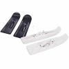
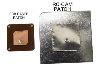
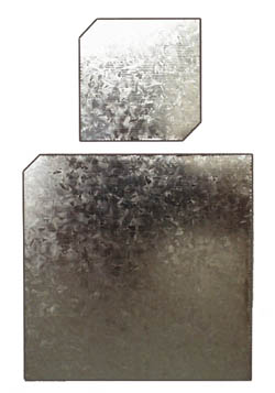
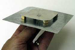
The antenna element is much larger on an air dielectric Patch. If you hold it up to a circuit board based antenna you will see that it is about 50% larger. Larger antennas, that are driven at resonance, have higher efficiency than those that are smaller. The photo on the right shows two 2.4GHz Patch antennas (the size difference is obvious).
Antenna modeling suggest that an air dielectric design can achieve gains in excess of 8dBi. This is a +6dB improvement over a traditional dipole and at least a +3dB advantage over most commercial Patch antennas. In a practical sense, every 3dB improvement in antenna performance will offer the same advantages as to doubling your transmitter's power. Now do I have your attention?
Tool Time
Very few tools and supplies are needed to build the Patch. You will need a 40 watt soldering iron, pair of tin snips or heavy shears, rubber cement or glue stick, epoxy adhesive or CA (crazy glue), a flat file, and a couple of drill bits (drill sizes shown on the downloadable plans).
Expected construction time is about a half hour. With practice, you can build one in ten minutes.
Three's a Crowd
There are only three materials needed to construct the antenna:
5" x 7" piece of 24 to 30 gauge sheet metal (tin, brass, or galvanized).
2 inch long piece of 0.20" square balsa, pine, or hardwood.
PCB mount SMA connector, Amphenol RFX #901-9895-RFX. Available at Mouser (p/n 523-901-9895-RFX ) and Digi-Key (ARFX1229).
I purchased the sheetmetal at the hardware store (Lowe's). It was found in the roofing area and is sold in a plastic bag as "Galvanized Step Flashing." A package of ten 5"x7" pieces cost only $1.50, so that breaks down to fifteen cents an antenna. As a side bonus, any leftovers can be used to fix your leaky roof. I guess patching roofs and making Patch antennas is all the same thing to the sheet metal.
Of course you do not need to use roof flashing. Low gauge sheets of brass or tin will work too. Avoid copper (too soft) and aluminum (can't solder to it). The local hobby store had some nice sheets of 0.008" tin, but they were only 4" wide, so I was unable to use it on the Patch's big reflector.
The sheet metal material you choose should be light enough so that you can cut it with your shears. But, it must also be sufficiently rigid so that your finished antenna holds its shape and survives some manhandling at the field. Heck, the lid from a large coffee can could be cut to size if you get desperate.
The wood is used as a controlled dielectric spacer. I bought some .25" square hardwood from the hardware store (36" long piece cost $0.60) and trimmed it to .20" thick. You can also use Teflon, Sturdyboard foam, or "microwave safe" plastic. Do NOT use metallic/conductive/ferrous material.
Design Documents:
Template File: .
Revision: Rev A, dated 10-01-2002
Let's Build the GP Patch
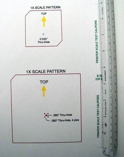
The first thing you need to do is download the full size template and print it out. Using a foot long ruler, confirm that the printed caliper graphic is exactly 9.0" in length. If it is off by more than 1% then change the print menu's scale factor setting and try again. Repeat until the scale is as close to 9.0" as you can get it.
Note: The printed plans must be checked for accurate scaling. Please be aware that some printers need compensation for best accuracy. Do NOT skip this step.
Now cut out the two full scale paper patterns. The red border should be fully intact (cut on the outside edge).
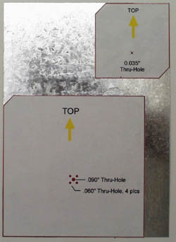
Apply the rubber cement (or paper glue stick) to the back of the patterns and then place them on your sheet metal. If you align them as shown in the photo then only two sides of each pattern will need to be cut.
Do not trace the patterns onto the metal. Take the time to glue them on. You must ensure that your final cuts will be accurate and dressmaker patterns are part of the goof-proofing process.
Using your tin snip shears, carefully cut out the two metal parts. All trimming must be on the outside edge of the paper pattern (leave the printed perimeter line intact). Pay extra attention when cutting the small element since its accuracy really counts.
Using a sharp pointed object (center-punch, nail, ice pick, etc.) carefully mark the center locations of the six holes. Using the drill bit sizes shown on the pattern, drill all the thru-holes. You may use a 1/16" bit for the .060" holes and a 3/32" for the .090".
Remove the paper patterns. By the way, the rubber cement is not permanent and your patterns will peel off with no residue. Glue stick adhesive will clean up with water. If you used any other adhesives then may the Glue Gods have mercy on your soul.
Now flatten and debur all the edges. Use a flat file to clean up any ragged stuff and slightly round all corners to prevent injury. Straighten any warps so that the panels are as flat as possible.
The SMA connector is installed on the backside of the large reflector plate. It should drop into your drilled holes and sit perfectly flush on the surface.
Solder the four ground legs on the front side. I found that clean galvanized steel or tin material flowed very well using a basic 40 watt iron and decent electronic solder.
After soldering, trim the SMA's four legs flush on the front side. Do NOT trim the center post.
The SMA's center post is a bit short and needs to be longer in order to reach the driven element when it is added in a future step. Merely solder a short piece of 24-26 AWG solid wire (a .5" long resistor lead works well) onto the end of the center post. When you are done it should extend the post by about a quarter inch.
Now clean off ALL the solder flux. Do not omit this step.
Now it's time to cut out the wood spacer blocks. You will need five pieces that are .20" square by about .25" long (5mm x 5mm x 6mm). The critical thing is to maintain the 0.20" dimension as close as you can since it will set the element spacing when the two metal parts are combined.
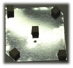
Using a small amount of epoxy or CA adhesive, glue the wood blocks to the center and four corners of the small element's bottom side. Place them on the sheet metal so that the .20" dimension (not the .25" side) sets their height . Allow the glue to dry. If you don't want to wait long then use fast cure 5-minute epoxy or CA.
Now its time for a dry fit of the two panels. Align the hole in the element over the SMA's extended post on the reflector. Slide the two parts together so that the SMA's center post passes through the small element panel.
The reflector's beveled corner (orientation mark) should be at the upper left. The element's two beveled corners should be at the upper left and lower right. The two panels should appear to be centered over each other with the SMA offset towards the bottom.
If you like the fit then remove the element and apply a small dab of epoxy to the top of the wood blocks. Put the two parts together again and ensure that they are perfectly centered.
While the glue is drying, solder the SMA's center post to the element. Be very careful or the little wire stub you added will come free from the SMA if its solder reflows. I suggest you solder it while the adhesive is still wet so that you can pull the panels apart if you run into trouble. Cut off the excess wire stub when you are done and allow the adhesive to cure.
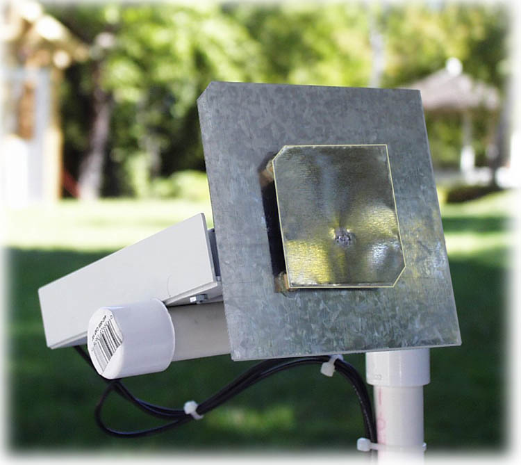
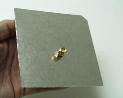
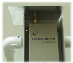
The antenna is now complete! Just screw it onto the SMA of your video receiver and aim it towards your R/C model. The arrow shown on the template is the orientation for use with transmitters with vertical polarization (e.g., vertical Tx whips). If yours is horizontally polarized then rotate the patch 90º.
The photo on the left shows the Patch screwed onto my video receiver. Other than the SMA coupling, nothing is holding the Patch. I will probably add a bracket to support it in order to prevent SMA connector damage.
By the way, the PVC stand works great -- construction details to it are available on the RC-CAM Field Equipment page.
 The antenna element is much larger on an air dielectric Patch. If you hold it up to a circuit board based antenna you will see that it is about 50% larger. Larger antennas, that are driven at resonance, have higher efficiency than those that are smaller. The photo on the right shows two 2.4GHz Patch antennas (the size difference is obvious).
 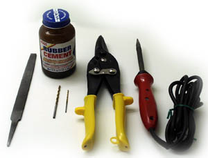 Very few tools and supplies are needed to build the Patch. You will need a 40 watt soldering iron, pair of tin snips or heavy shears, rubber cement or glue stick, epoxy adhesive or CA (crazy glue), a flat file, and a couple of drill bits (drill sizes shown on the downloadable plans).
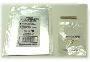
 The antenna is now complete! Just screw it onto the SMA of your video receiver and aim it towards your R/C model. The arrow shown on the template is the orientation for use with transmitters with vertical polarization (e.g., vertical Tx whips). If yours is horizontally polarized then rotate the patch 90º.